Tips for Method Development in 3-Point Pending DMA Measurements
In the 3-point bending mode, an offset force has to be specified in the method in addition to the maximum displacement and force amplitudes. In this article, we describe a possible procedure for determining the offset force and the other measurement parameters. We also estimate the uncertainty of the resulting 3-point bending modulus values.
Introduction
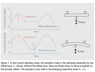
Ceramics, metals and composite materials are usually measured in DMA in the 3-point bending mode (see Figure 1). In this mode, the sample is held in position in the clamping assembly by an offset force (preload force) applied to the sample. The offset force must be greater than the amplitude of the force applied to the sample otherwise the sample will lose contact with the clamping assembly. In 3-point bending measurements, the offset force is usually provided as a “constant current offset force” (details are given in the next section).
In this article, we explain how measurement parameters can be determined for 3-point bending experiments. We also estimate the uncertainty of the resulting 3-point bending modulus values.
The Different Offset Control Modes in the DMA861e
Constant Current Offset Control Mode
In the Constant Current Offset control mode, the drive motor generates a constant offset force, Fcc, in addition to the dynamic force with amplitude FA. The force generated by the drive motor is applied to the sample via a membrane. The membrane and the sample (with the sample holder and the drive shaft) are connected in parallel. Part of Fcc is therefore used to deform the membrane. If the stiffness of the sample is more than twice the stiffness of the membrane, then practically the entire offset force, Fcc, is applied to the sample. The stiffness of the membrane is determined during the mechanical adjustment of the instrument and is typically about 6 N/mm for the 40-N drive motor and about 3 N/mm for the 12-N or 18-N drive motors. This means that from a sample stiffness of about 12 N/mm or more, the entire offset force is applied to the sample.
If the sample stiffness is about the same as that of the drive motor membrane, the offset force actually exerted on the sample is reduced by half. With softer samples, it is correspondingly smaller. To a certain extent, this effect can be made use of when the sample softens during a glass transition. The offset force actually applied decreases and the predeformation of the sample is reduced making it possible to measure softer samples.
The “Force Offset” measurement curve that can be displayed in the Evaluation Window is the static offset force actually exerted on the sample. The constant current offset mode is mainly used for experiments in 3-point bending. If the samples are sufficiently stiff (above 12 N/mm), the force specified in the method corresponds to the offset force acting on the sample.
The force amplitude is not influenced by the membrane because if necessary it is controlled by the force sensor.
The sample stiffness, Ss, is given by
Ss = E/G (1)
where E is the modulus of the sample and g the geometry factor. For a rectangular bar, the geometry factor in 3-point bending is given by
g= 13/4*b*h3
Here l, b and h are the dimensions of the sample (l = clamping length, b = width, h = thickness).
Autooffset Control Mode
In the Autooffset control mode, the offset force just sufficient to hold the sample in place during the measurement is first determined (autooffset = 100%; this corresponds to the condition Fs = FA (see Figure 1)).
 |
Conclusions
- The optimum displacement amplitude is typically between about 20 µm (for samples with smooth flat surfaces, e.g. metals) and 100 µm (for samples with rough surfaces, e.g. composite materials such as the printed circuit board measured here)
- The constant current offset force specified in the measurement method, Fcc, is shared between the membrane and the sample. If the sample stiffness is larger than about 12 N/mm, Fcc is applied practically completely to the sample. With samples whose stiffness is about the same as that of the stiffness of the membrane of the drive motor, the offset force actually applied to the sample is about half of Fcc. The other half is used to deform the membrane. In this case, with temperature-dependent measurements, the offset force exerted on the sample automatically adapts to the sample stiffness during the experiment. For the constant current offset mode the sample stiffness should ideally be between about 12 N/mm and one fifth of the sample holder stiffness (see Table 1).
- To determine the optimum constant current offset force, Fcc, a trial experiment should be performed under isothermal conditions (e.g. at room temperature). In this experiment, Fcc is varied under constant dynamic measurement conditions. A typical method is shown in Figure 3. Depending on the stiffness and the nature of the surface of the sample, Fcc is typically about two to ten times larger than the dynamic force amplitude. To provide this relatively large static offset force, it is best to use a 40-N drive motor for 3-point bending. It should be noted that the 40-N drive motor provides a maximum static force of about 25 N (the 40 N relates to the maximum dynamic force amplitude). Similarly, with the 12-N and 18-N drive motors, maximum constant current offset forces of about 8 N and 12 N are available.
- Quality criterion for optimum parameters: the tan d values should be as small as possible and independent of the constant current offset force.
- Although the predeformation of the sample might be clearly visible, the sample strain that actually occurs is in the per thousand range.
- The accuracy with which the modulus value can be determined depends mainly on the accuracy with which the sample geometry can be specified. Even with geometrically well defined samples (standard deviation for clamping length, width and thickness each 0.05 mm) standard deviations for the modulus value of the order of 10% are obtained.
Tips on Method Development for DMA Measurements in 3-Point Bending | Thermal Analysis Application No. UC 283 | Application published in METTLER TOLEDO Thermal Analysis UserCom 28